Arduino IDE
- ¿Qué es Arduino IDE?
- Preparar Arduino IDE para Alvik: Instalar Placa ESP32 y libreria Arduino Avik
- Preparar ALVIK para Arduino IDE: Modo Bootloader
- Arduino IDE sin IoT: Un pequeña danza
- Arduino IDE sin IoT: Evita obstáculos
- Arduino IDE sin IoT: Coche a control remoto
- Internet de las cosas IoT
- Arduino IDE con IoT: Escaneo Wifi
- Arduino IDE con IoT: Arduino Cloud
- Arduino IDE con IoT: Coche teledirigido
- GPIO del ESP32
- Arduino IDE con IoT: ESP32 + Sensores externos + IoT
- Predictor meteorológico
¿Qué es Arduino IDE?
Necesitarás el entorno de desarrollo Arduino IDE (IDE, Integrated development environment) (aquí https://www.arduino.cc/en/Main/Software para descargártelo)
En Linux puede salir este mensaje "can't open device "/dev/ttyUSB0": Permission denied" donde 0 puede ser otro número, la solución aquí
Está constituido por un editor de texto para escribir el código, un área de mensajes, una barra de herramientas con botones para las funciones comunes, y una serie de menús.
Arduino utiliza para escribir el código fuente o programa de aplicación lo que denomina "sketch" (programa). Estos programas son escritos en el editor de texto. Existe la posibilidad de cortar/pegar y buscar/remplazar texto.

Preparar Arduino IDE para Alvik: Instalar Placa ESP32 y libreria Arduino Avik
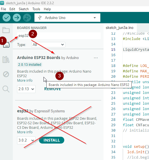
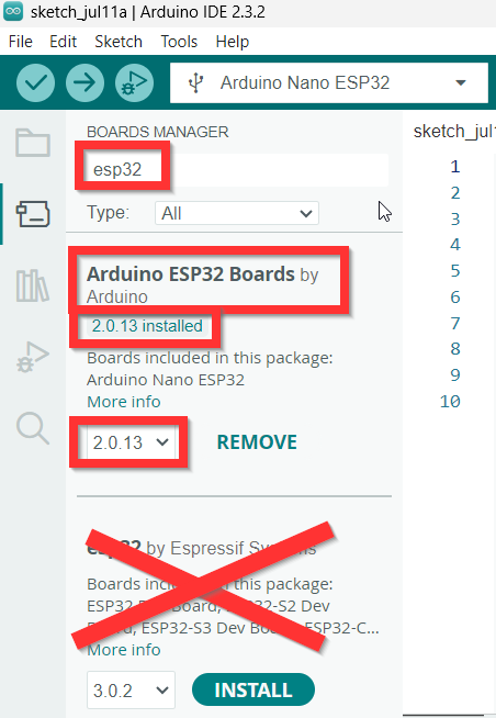
Instalar placa Arduino ESP32 Boards by Arduino
Lo primero que tenemos que hacer es instalar la placa Arduino ESP32 tal y como dice esta captura
O este vídeo a partir de 9:30 (pongo el vídeo pues es interesante si quieres aprender más sobre Arduino ESP32)
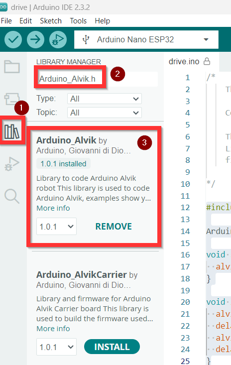
Instalar Librería Arduino_Alvik.h
Las funciones que tiene la librería son prácticamente las vistas en las APIs, ver https://libros.catedu.es/books/arduino-alvik/page/arduino-alvik-api
Para ejecutarlo en el Arduino IDE tenemos que tener esta librería que es fácilmente instalable:
Tal y como dice https://docs.arduino.cc/tutorials/alvik/setting-alvik-arduino-ide/
- Arduino_Alvik: Esta es la librería principal que usaremos en nuestros programas y contiene comandos de alto nivel para controlar el "cerebro" del Alvik, que es la placa Nano ESP32.
- Arduino_AlvikCarrier: Esta biblioteca está diseñada para la placa STM del dispositivo y resulta útil en situaciones donde se requiere un control más preciso de los comandos. Permite desarrollos más complejos, especialmente cuando se requiere una mayor integración con el hardware. Fuera del contexto de este curso.
Preparar ALVIK para Arduino IDE: Modo Bootloader
¿Qué es eso del Boodloader? Es un pequeño programa que esta en el microcontrolador (Arduino, ESP32, etc...) que permite que arranque la placa y espere las instrucciones del programa del usuario, digamos que es como un "pequeño sistema operativo de arranque" por ejemplo en el Arduino, se ejecuta en un poco de tiempo cuando arranca la placa o se resetea, y espera el programa IDE por el puerto USB, si llega (él comprueba que es un IDE y no otra cosa) lo almacena en un sitio de la memoria Flash y lo ejecuta, sino, pues ejecuta el que ya esta cargado. El bootloader hace que parpadee el led 13 de un Arduino UNO y se reserva un trozo de memoria para el Bootloader (en el Arduino UNO ocupa sólo 0.5K de los 32K que tiene disponibles el micro para ello). En nuestro caso el ESP32 Nano Arduino igual pero cuando cargamos el micropython nos cargamos ese bootloader por otro que tiene el compilador microPython. Lo de "quemar" o "flashear" el bootlader nos lo podemos encontrar en los cursos de Aularagón en el Zigbee de domótica con Raspberry, o a la hora de quemar el Nano Arduino como Arduino UNO en el curso de mClon
Tal y como dice en https://docs.arduino.cc/tutorials/alvik/setting-alvik-arduino-ide/
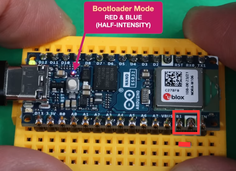
- cortocircuitar B1 y GND

Yo lo hago con un destornillador y toco las dos puntas, con cuidado de no tocar nada más. - Mientras esta cortocircuitado PULSA EL BOTÓN RESET

- Soltar botón y cortocircuito pines B1 y GND y se queda el led de la placa ESP32 en color púrpura ver figura del paso 1, si no se queda púrpura, repetir el proceso paciencia
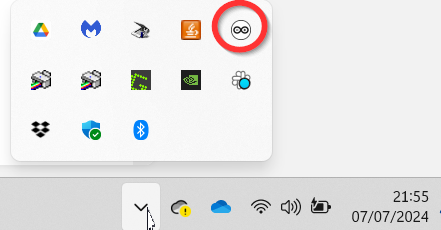
- Abrir el programa ARDUINO IDE PERO CERRAR OTROS
(como el Arduino Create Agent que se queda en segundo plano abajo a la derecha , el MicroPython Installer....)
- Asegurarse que esta instalado la placa Arduino ESP32 correctamente al menos la versión 2.013
(ir a Tools-Boards-BoardManager) si hay una versión anterior, desinstalar el que hay (remove) e instalarlo de nuevo.
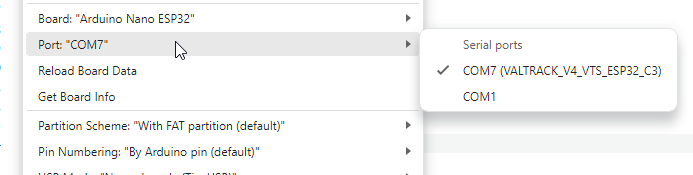
- Ir a Tools-Port y seleccionar el puerto, habrá cambiado a uno nuevo, puede ser algo parecido a esto :

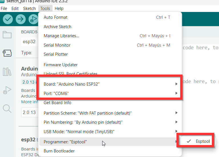
- Ir a Tools > Board - Arduino ESP32 Boards > Arduino Nano ESP32 (o esp32 > Arduino Nano ESP32 )
- Poner Tools-> Programmer- seleccionar ESPTOOL

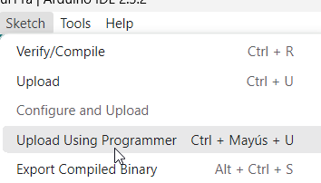
- Sketch > Upload Using Programmer

- Cuando salga este mensaje pasar al paso 11
Leaving... Hard resetting via RTS pin... - Apretar el botón RESET y ya puedes o ejecutar un programa en Arduino IDE o instalar MicroPython

Curiosidad:
¿Por qué al poner la placa en modo Bootloader o cada vez que enciendo Arduino Alvik se enciende y se apaga el led RGB de al lado con los colores Rojo y Verde?
Solución https://libros.catedu.es/books/arduino-alvik/page/gpio-del-esp32-lD7
P: ¿No hay otra forma que no sea meter el destornillador y cortocircuitar los pines B1 y GND?
R: Si, hemos elegido la anterior pues nos parece más rápida y sencilla pero en https://github.com/arduino-libraries/Arduino_Alvik?tab=readme-ov-file#how-to-update-firmware-of-arduino-alvik-carrier tienes otro método utilizado el programa STM32 Cube Programer
Arduino IDE sin IoT: Un pequeña danza
En la pagina https://www.arduinolibraries.info/libraries/arduino_alvik o desde https://github.com/arduino-libraries/Arduino_Alvik podemos descargarnos multitud de ejemplos de código escrito en Arduino IDE para manejar este robot
Una pequeña danza
Este sencillo programa hace mover el robot a una velocidad de 10 y va cambiando el giro de 45º a -45º cada segundo
#include "Arduino_Alvik.h"
Arduino_Alvik alvik;
void setup() {
alvik.begin();
}
void loop() {
alvik.drive(10, 45);
delay(10000);
alvik.drive(10, -45);
delay(10000);
}y da este error NO DEU dfu-util: No DFU capable USB device available Failed uploading: uploading error: exist status 74 ¿Por qué?
No has preparado convenientemente el ALVIK haz https://libros.catedu.es/books/arduino-alvik/page/preparar-alvik-para-arduino-ide-modo-bootloader
Resultado
Arduino IDE sin IoT: Evita obstáculos
En la pagina https://www.arduinolibraries.info/libraries/arduino_alvik o desde https://github.com/arduino-libraries/Arduino_Alvik podemos descargarnos multitud de ejemplos de código escrito en Arduino IDE para manejar este robot
Evita obstáculos
Este sencillo programa hace mover el robot evitando obstáculos
#include "Arduino_Alvik.h"
Arduino_Alvik alvik;
void setup() {
alvik.begin();
delay(5000); // Waiting for the robot to setup
}
void loop() {
float distance = 12.0;
float degrees = 45.0;
float speed = 10.0;
float distance_l, distance_cl, distance_c, distance_r, distance_cr;
alvik.get_distance(distance_l, distance_cl, distance_c, distance_r, distance_cr);
delay(50);
Serial.println(distance_c);
if (distance_c < distance || distance_cl < distance || distance_cr < distance || distance_l < distance || distance_r < distance) {
alvik.rotate(degrees);
} else {
alvik.drive(speed, 0.0);
}
}y da este error NO DEU dfu-util: No DFU capable USB device available Failed uploading: uploading error: exist status 74 ¿Por qué?
No has preparado convenientemente el ALVIK haz https://libros.catedu.es/books/arduino-alvik/page/preparar-alvik-para-arduino-ide-modo-bootloaderResultado
Reto
Tienes muchos ejemplos en https://github.com/arduino-libraries/Arduino_Alvik/tree/main/examples
🫵🫵🫵🫵 ¿ A QUE ESPERAS? 🫵🫵🫵
Arduino IDE sin IoT: Coche a control remoto
Más adelante verás un coche teledirigido con el móvil y usando internet.
Pero en este caso vamos a usar DOS ARDUINOS ALVIKS uno como receptor y otro con envío de órdenes
La fuente de este programa lo puedes encontrar en https://github.com/arduino-libraries/Arduino_Alvik/blob/main/examples/remote_control/remote_control.ino
Se graban los dos programas en los dos alviks, y al apretar OK uno es el que envía la órdenes y el otro le apretamos CANCEL y es el receptor
Es muy curioso que la comunicación lo hace via Wifi pero sin usar ningún punto de acceso exterior, sino entre ellos comunicación pareada (peer)
/*
This file is part of the Arduino_Alvik library.
Copyright (c) 2024 Arduino SA
This Source Code Form is subject to the terms of the Mozilla Public
License, v. 2.0. If a copy of the MPL was not distributed with this
file, You can obtain one at http://mozilla.org/MPL/2.0/.
*/
// This example shows how to interface 2 Alvik robots via ESPnow.
// At startup, you can select if an Alvik is a trasmitter by pressing the "check button" or a receiver by pressing "cancel button". Use arrows to move the robot.
#include "Arduino_Alvik.h"
#include <esp_now.h>
#include <WiFi.h>
Arduino_Alvik alvik;
uint8_t broadcastAddress[] = {0xFF, 0xFF, 0xFF, 0xFF, 0xFF, 0xFF};
uint8_t myData;
esp_now_peer_info_t peerInfo;
int alvik_mode = -1; // 0 is receiver, 1 is sender
bool led_blink = false;
void setup() {
Serial.begin(115200);
while((!Serial)&&(millis()>3000));
alvik.begin();
WiFi.mode(WIFI_STA);
if (esp_now_init() != ESP_OK) {
Serial.println("Error initializing ESP-NOW");
return;
}
while (alvik_mode == -1){
if (alvik.get_touch_cancel()){
alvik_mode = 0;
}
if (alvik.get_touch_ok()){
alvik_mode = 1;
}
}
if (alvik_mode == 0){
esp_now_register_recv_cb(OnDataRecv);
}
else{
memcpy(peerInfo.peer_addr, broadcastAddress, 6);
peerInfo.channel = 0;
peerInfo.encrypt = false;
if (esp_now_add_peer(&peerInfo) != ESP_OK){
Serial.println("Failed to add peer");
return;
}
}
}
void loop() {
if (alvik_mode==0){
alvik.left_led.set_color(led_blink, !led_blink, 0);
alvik.right_led.set_color(!led_blink, led_blink, 0);
delay(500);
}
else{
if (alvik.get_touch_any()){
if (alvik.get_touch_up()){
myData = 'F';
esp_now_send(broadcastAddress, (uint8_t *) &myData, sizeof(myData));
}
if (alvik.get_touch_down()){
myData = 'B';
esp_now_send(broadcastAddress, (uint8_t *) &myData, sizeof(myData));
}
if (alvik.get_touch_left()){
myData = 'L';
esp_now_send(broadcastAddress, (uint8_t *) &myData, sizeof(myData));
}
if (alvik.get_touch_right()){
myData = 'R';
esp_now_send(broadcastAddress, (uint8_t *) &myData, sizeof(myData));
}
if (alvik.get_touch_center()){
myData = 'S';
esp_now_send(broadcastAddress, (uint8_t *) &myData, sizeof(myData));
}
}
alvik.left_led.set_color(0, 0, led_blink);
alvik.right_led.set_color(0, 0, led_blink);
delay(100);
}
led_blink = !led_blink;
}
void OnDataRecv(const uint8_t * mac, const uint8_t *incomingData, int len){
Serial.print(incomingData[0]);
switch (incomingData[0]){
case 'F':
alvik.drive(7, 0);
break;
case 'B':
alvik.drive(-7, 0);
break;
case 'L':
alvik.drive(0, 45);
break;
case 'R':
alvik.drive(0, -45);
break;
case 'S':
alvik.brake();
break;
}
Serial.println();
}El resultado es expectacular
Internet de las cosas IoT
El Internet de las cosas (Internet of Thing IoT) describe objetos físicos —o grupos de estos— con sensores, capacidad de procesamiento, software y otras tecnologías que se conectan e intercambian datos con otros dispositivos y sistemas a través de internet u otras redes de comunicación. El Internet de las cosas se ha considerado un término erróneo porque los dispositivos no necesitan estar conectados a la Internet pública. Sólo necesitan estar conectadas a una red y ser direccionables individualmente
Fuente Wikipedia IoT Internet de las cosas CC-BY-SA

De Drawed by Wilgengebroed on FlickrTranslated by Prades97 CC BY-SA 3.0
Estamos hablando de dispositivos que se conectan a internet de forma desatendida, por vía hardware (o mejor dicho firmware) a diferencia de un ordenador, tablet o móvil, donde tienes que configurar por software el dispositivo y hay un diálogo entre usuario y dispositivo sobre el uso de Internet (el software solicita tal página web, tales datos etc por voluntad del usuario o por diálogo con el usuario) Aquí los dispositivos están ya configurados de los datos que se comunican. Es decir "conectar y olvidar".
Piensa en la diferencia entre un enchufe inteligente y un ordenador, el primero es lo que se considera dentro de IoT
Desventajas: El acceso a Internet de dispositivos caseros puede generar problemas a nivel mundial:
- el caso Mirai
- aspiradores que nos espían
IoT en los cursos de Aularagón
- Blynk: lo que nos gusta de esta herramienta es que es casi "instantánea" o "síncrona". Esto es imprescindible con ciertos robots como el Rover Marciano con Arduino. Necesitamos que "gire" para evitar un obstáculo, no podemos esperar !!!. Veremos con BLYNK un protocolo que entre el dispositivo electrónico (nuestro robot) y nosotros (en ordenador, en una APP en el móvil) la comunicación es instantánea, gracias a un servidor que hará de intermedio, que puede ser local (BLYNK LEGACY) o en Internet (BLYNK IoT).
- Blynk legacy es la que se va a trabajar en
- Blynk IoT es la que se va a trabajar con
- ThinkSpeak y SmartioSpace
- MQTT El emisor envía datos, se almacenan en un servidor, y cuando puede, lo vuelca al cliente. Cliente y emisor pueden ser el dispositivo electrónico y nosotros o viceversa. Veremos que esto es lo que hace el protocolo MQTT y está tremendamente extendido por lo barato y fácil que es. Hace que los servidores no estén tan ocupados, por lo tanto hay varios proveedores que ofrecen este servicio gratuitamente. Hay robots como los que tienen la placa TDR STEAM IMAGINA que envía datos de temperatura, humedad, .. y pueden recibir datos pero no precisan de esta exigencia instantánea como un rover.
- TELEGRAM
- Arduino cloud IoT
- Cyberpi y mBot2
Arduino IDE con IoT: Escaneo Wifi
Desde https://github.com/espressif/arduino-esp32/blob/master/libraries/WiFi/examples/WiFiScan/WiFiScan.ino podemos encontrar este programa para escanear las redes wifi desde nuestro ESP32 Arduino
https://app.arduino.cc/sketches/54b6f875-2961-4ec5-8a48-608d9dde5feb?view-mode=preview
y da este error NO DEU dfu-util: No DFU capable USB device available Failed uploading: uploading error: exist status 74 ¿Por qué?
No has preparado convenientemente el ALVIK haz https://libros.catedu.es/books/arduino-alvik/page/preparar-alvik-para-arduino-ide-modo-bootloader
Instalando la librería Wifi.h
Te dará un error de compilación pues no tiene esta librería. Puedes descargar la versión última desde https://www.arduino.cc/reference/en/libraries/wifi/
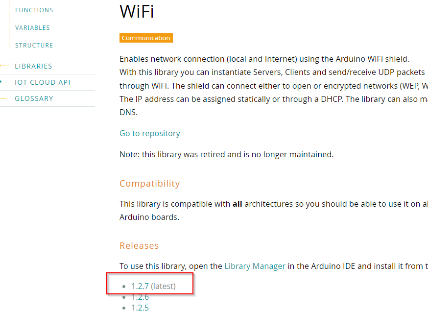
Una vez descargada (un fichero ZIP no lo descomprimas) en el editor Arduino IDE se instala desde este menú
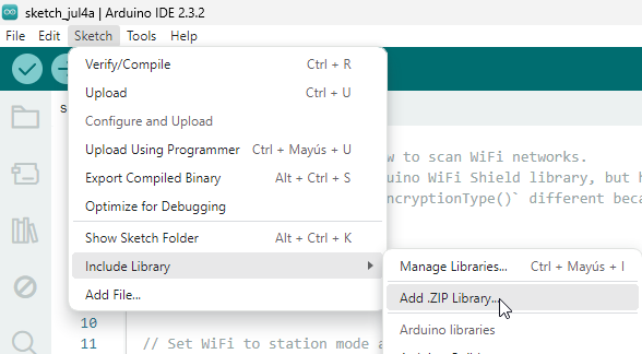
Seleccionamos el fichero Zip que has descargado y ya tenemos la librería instalada
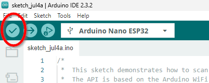
Compilamos
Antes de compilar CONECTAMOS NUESTRO ESP32
Licencia CC-BY-NC-SA origen https://courses.arduino.cc/explore-robotics-micropython/lessons/getting-started/
No hace falta encender el robot Arduino Alvik
Y seleccionamos la placa que ha reconocido

Y ya se puede compilar !!! no tiene que dar ningún fallo
Subirlo al ESP32
Pues si lo intentas subir
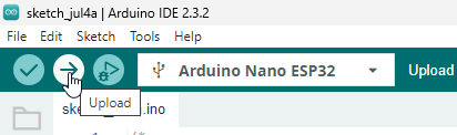
y da este error NO DEU dfu-util: No DFU capable USB device available Failed uploading: uploading error: exist status 74 ¿Por qué?
Lee https://libros.catedu.es/books/arduino-alvik/page/modo-bootloader
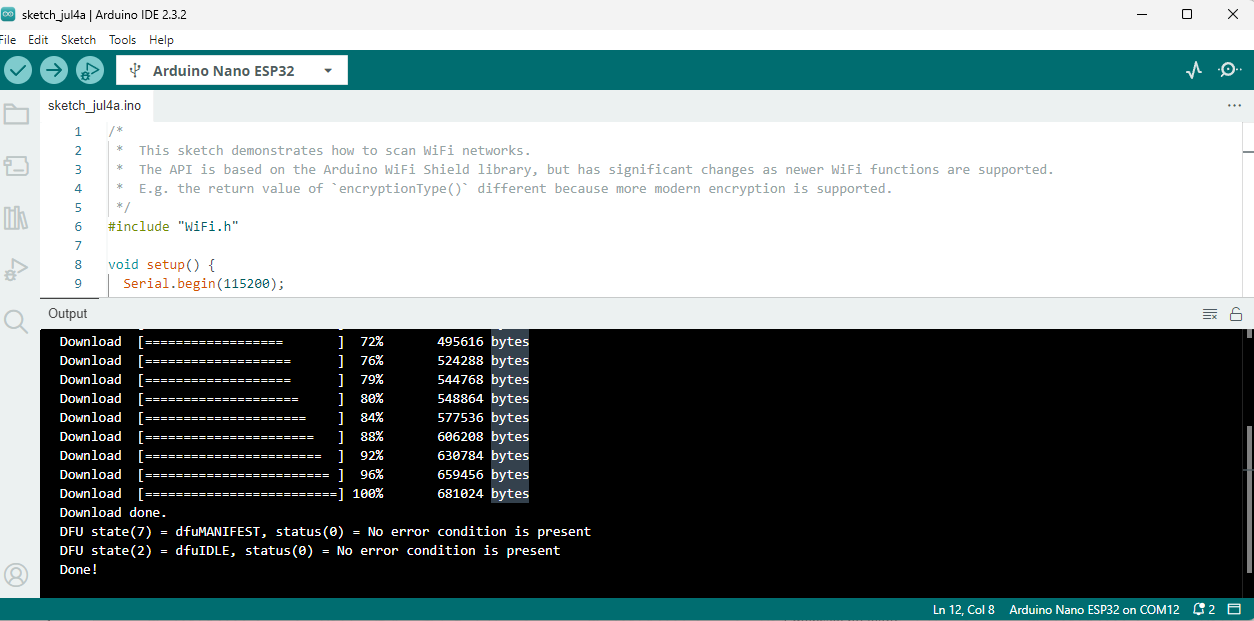
Resultado
Le damos a subir, y en la ventana de Output da como correcto
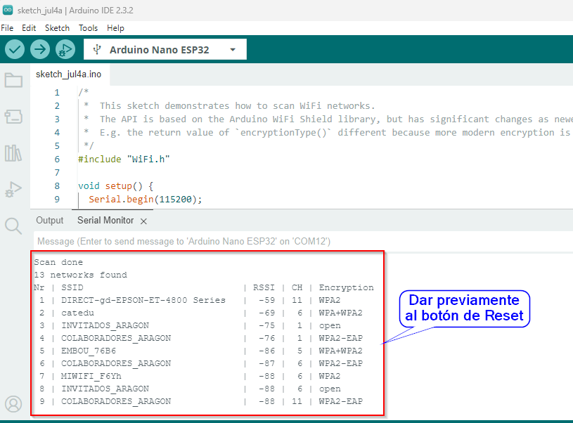
Y si nos vamos a la ventana del monitor serie
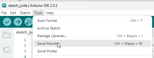
No nos sale nada !!! le das al botón de reset y ya sale :
¿Puedo ahora ejecutar un programa en MicroPyhon?
No, tal y como dice aquí https://libros.catedu.es/books/arduino-alvik/page/instalar-micropython tienes que instalar el interpretador/compilador de Micropython dentro del ESP32, sino Arduino Lab for Micropython no se podrá conectar porque no lo encontrará.
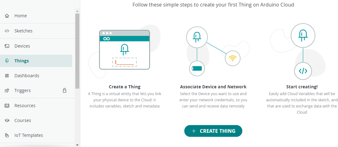
Arduino IDE con IoT: Arduino Cloud
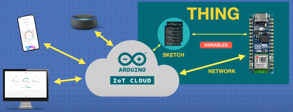
Esta plataforma https://docs.arduino.cc/arduino-cloud/ nos permite conectar nuestras placas (Arduino v4, ESP32, et...) con un panel de control Dashboard y así controlarlos a distancia por Internet.
El mecanismo es sencillo, el ESP32 conectado por internet, pasa variables a un código (Sketch), a este conjunto se le llama Thing, y este se lo comunica a IoT CLOUD y la plataforma lo comunica a los paneles de control. Dashboard que se puede ver desde el PC o desde el móvil El proceso también funciona al revés.
 Extraído de Youtube Exploring the Arduino Nano ESP32
- Creamos una cuenta en Arduino Cloud
- Instalamos Arduino Create Agent
- Build the Thing es decir preparamos nuestra placa ESP32 con el Sketch
- Creamos the device
- Creamos the thing
- Añadimos las variables
- Creamos el scketch y lo grabamos en el ESP32
- Construimos un Dashboard o panel de control
PASO 1 LOGUEARSE EN ARDUINO CLOUD
En Plan permite una cuenta gratuita sólo se pueden 2 things ver https://cloud.arduino.cc/plans
PASO 2 ADRUINO CREATE AGENT
Arduino Create Agent te lo puedes descargar desde https://cloud.arduino.cc/download-agent, se descarga, se ejecuta, hay que seguir los pasos, se queda en segundo plano en el PC y no tienes que preocuparte

PASO 3 Build the Thing: CREATE DEVICE
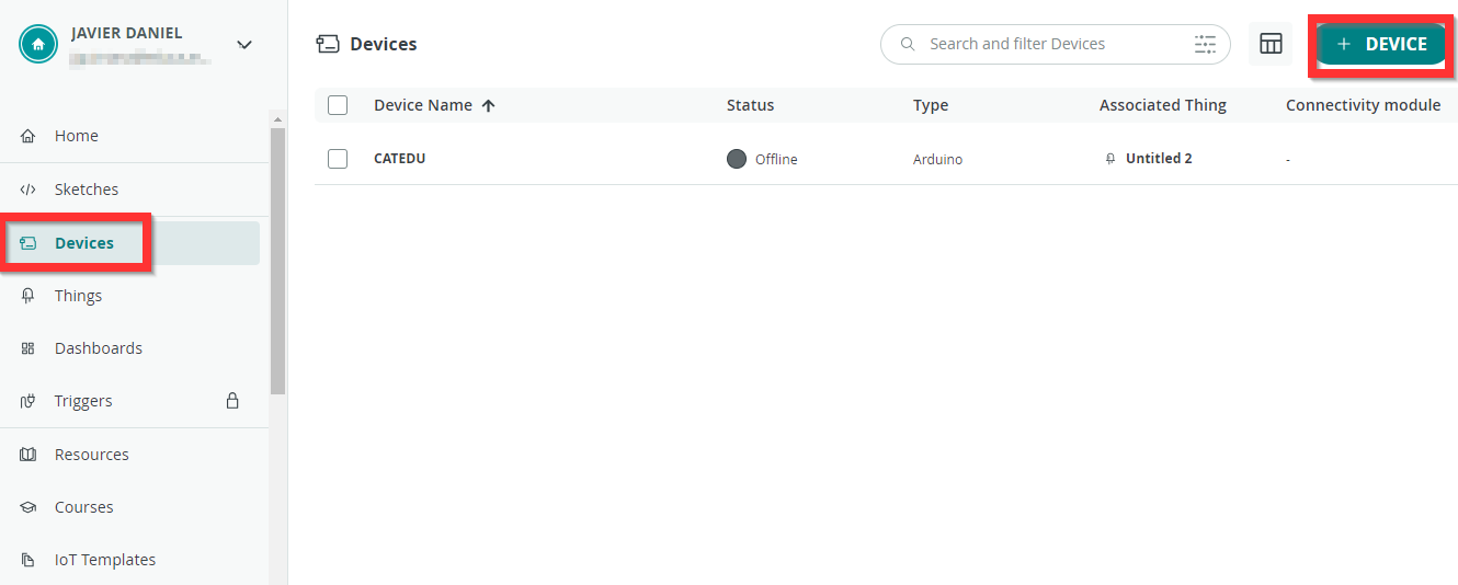
Primero añadimos un Device o placa en https://app.arduino.cc/devices
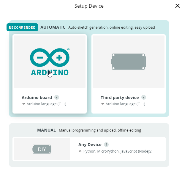
Elegimos placa Arduino
Si falla, ponemos la placa en modo Bootloader (ver qué es eso en https://libros.catedu.es/books/arduino-alvik/page/instalar-micropython ) y entonces detectará el puerto
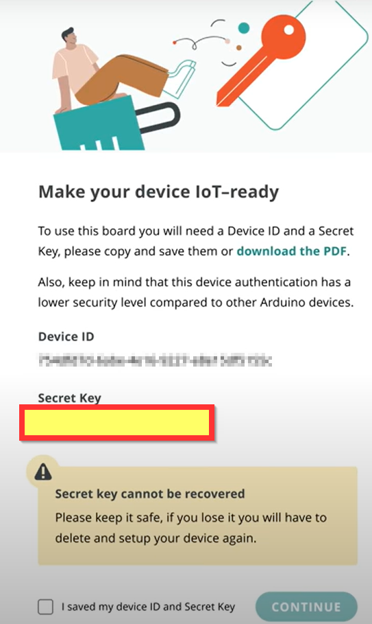
Conectamos nuestro Arduino Alvik y saldrá un diálogo con un TOKEN on Secret key que lo guardaremos ante todo no hacerlo público
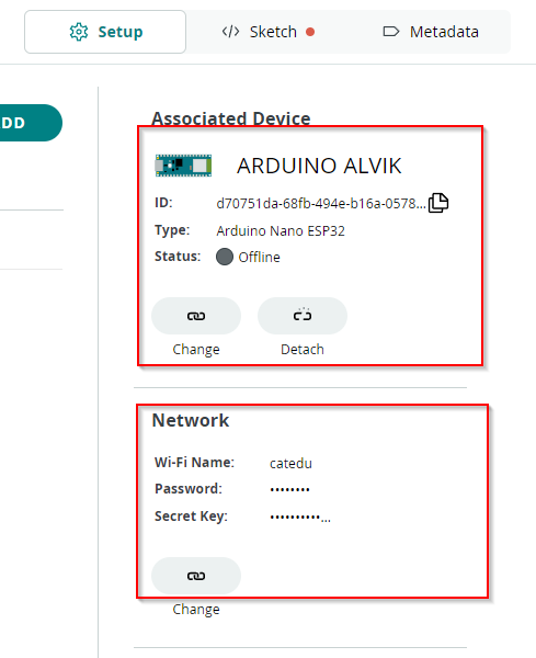
PASO 3 Build the Thing: CREATE THING
Una vez creada la placa, nos vamos a Thing, crear
Asociamos el Thing al Device, y le configuramos una red wifi (te predirá el Secret Key)
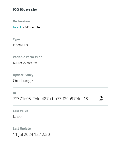
PASO 3 Build the Thing: CREATE THING-VARIABLES
Luego añadimos variables, por ejemplo RGBverde que va a encender y apagar la luz verde, va a ser tipo Bool y Read&Write
PASO 3 Build the Thing: CREATE THING-SKETCH
Dentro de Thinks nos vamos a SKETCH
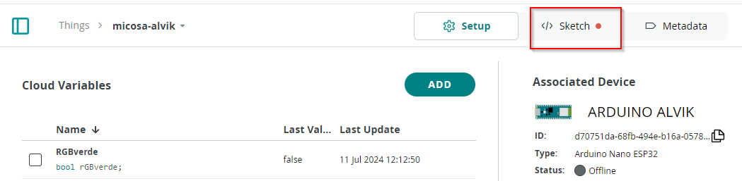
y vemos que ha creado un código thingProperties.h que tiene que tener el SSID de la wifi, su contraseña y la palabra clave de nuestro ESP32, podemos ponerlo manualmente o nos fijamos y en Secret Tab estan ya puestos :

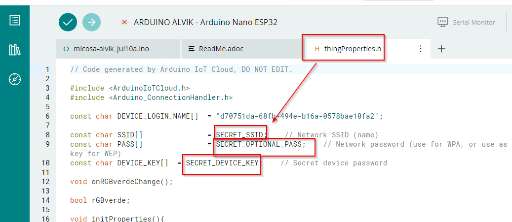
El otro script es el nombre que hemos creado en Thing y vemos que :
- LINEA 9 Esta declarada la variable que hemos añadido
- LINEA 16 Incluye la librería thingProperties.h
- LINEA 41 Añadimos en setup() la declaración que D13 SERÁ SALIDA pinMode(D13,OUTPUT);
- LINEA 60 AL 66 Añadimos en onRGBverdeChange una condicional, de tal manera que si la variable es cierta, que encienda el led y si es falsa que lo apague
¿Por qué es D13? ¿NO TENDRÍA QUE SER 48?
Eso ya lo hemos visto en https://libros.catedu.es/books/arduino-alvik/page/parpadeo-led-esp32
/*
Sketch generated by the Arduino IoT Cloud Thing "Untitled"
https://create.arduino.cc/cloud/things/34a0aae1-c7b9-42ab-92d4-0e37bd51031f
Arduino IoT Cloud Variables description
The following variables are automatically generated and updated when changes are made to the Thing
bool rGBverde;
Variables which are marked as READ/WRITE in the Cloud Thing will also have functions
which are called when their values are changed from the Dashboard.
These functions are generated with the Thing and added at the end of this sketch.
*/
#include "thingProperties.h"
void setup() {
// Initialize serial and wait for port to open:
Serial.begin(9600);
// This delay gives the chance to wait for a Serial Monitor without blocking if none is found
delay(1500);
// Defined in thingProperties.h
initProperties();
// Connect to Arduino IoT Cloud
ArduinoCloud.begin(ArduinoIoTPreferredConnection);
/*
The following function allows you to obtain more information
related to the state of network and IoT Cloud connection and errors
the higher number the more granular information you’ll get.
The default is 0 (only errors).
Maximum is 4
*/
setDebugMessageLevel(2);
ArduinoCloud.printDebugInfo();
/// MI CODIGO
pinMode(D13,OUTPUT);
}
void loop() {
ArduinoCloud.update();
// Your code here
}
/*
Since RGBverde is READ_WRITE variable, onRGBverdeChange() is
executed every time a new value is received from IoT Cloud.
*/
void onRGBverdeChange() {
// Add your code here to act upon RGBverde change
if (rGBverde){
digitalWrite(D13,HIGH);
}else{
digitalWrite(D13,LOW);
}
}
/*
Since RGBrojo is READ_WRITE variable, onRGBrojoChange() is
executed every time a new value is received from IoT Cloud.
*/
void onRGBrojoChange() {
// Add your code here to act upon RGBrojo change
}Lo subimos
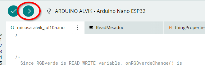
Ojo, tienes que tener el Arduino Arduino Create Agent paso 2
PASO 4 Dashboard
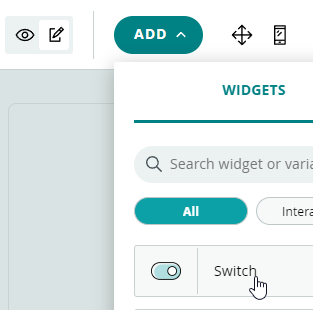
Creamos un panel de control

Y le añadimos un Switch asociado a la variable RGBverde
Podemos ver el dashboard en un teléfono móvil instalando la APP Arduino IoT Cloud Remote
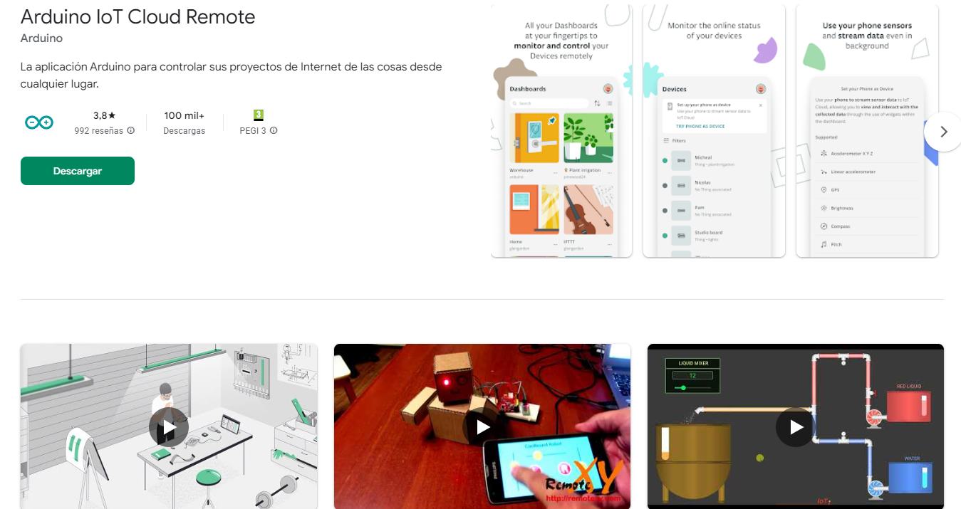
Al loguearse con tu cuenta, ya nos aparece el Dashboard
Resultado
Arduino IDE con IoT: Coche teledirigido
Aprovechamos el programa que enciende y apaga un led por Arduino Cloud
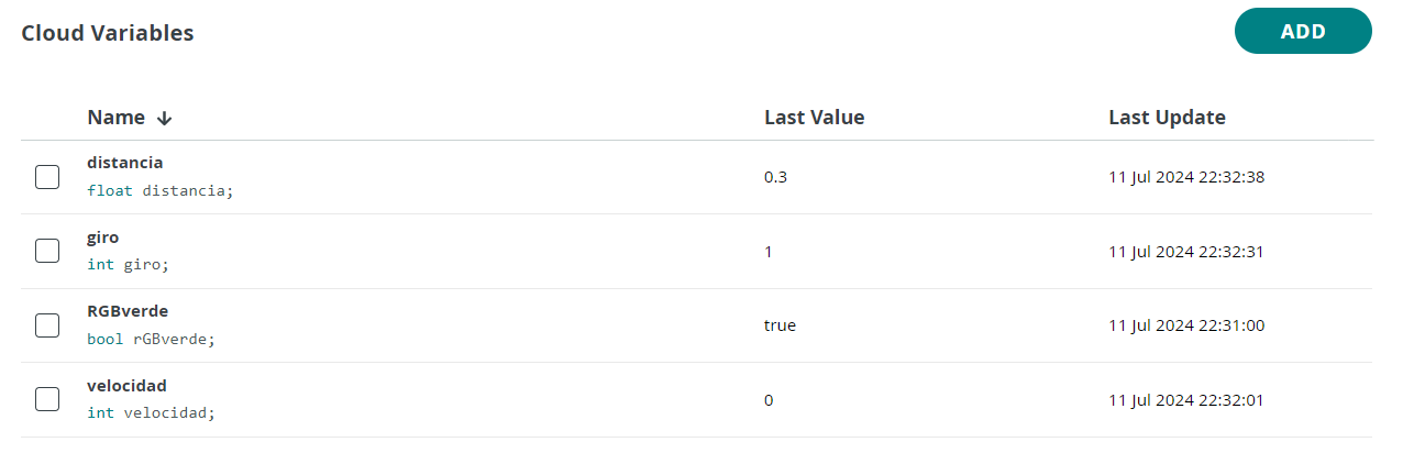
Variables
Le añadimos tres variables más :
- velocidad tipo entero Read&Write
- giro tipo entero Read&Write
- distancia tipo float Read
Sketch
En thingProperties.h añade automáticamente estas variables y funciones, no tienes que añadirlas :
void onGiroChange();
void onVelocidadChange();
void onRGBverdeChange();
float distancia;
int giro;
int velocidad;
bool rGBverde;Pero en la función principal, nosotros vamos a poner el siguiente código :
- Línea 2 #include "Arduino_Alvik.h" para que incluya la libería de manejo del robot
- Línea 4 Creamos un objeto alvik Arduino_Alvik alvik;
- Línea 6 Creamos una variable tipo array de 5 elementos para almacenar las distancias que lee el sensor de distancia float distances[5];
- Línea 15 arrancamos el objeto alvik alvik.begin();
- Línea 41 que el alvik se mueva según la velocidad y el giro alvik.drive(velocidad,giro);
- Es la instrucción principal y qué sencilla 😍
- Línea 42 leemos el array de distancias alvik.get_distance(distances[0], distances[1], distances[2], distances[3], distances[4]);
- Línea 43 de todas las distancias, sólo nos importa la 2 distancia=distances[2];
Nota: la instrucción 41 se han colocado dentro de loop() pero también se podría haber colocado dentro de onGiroChange();
onVelocidadChange();
#include "thingProperties.h"
#include "Arduino_Alvik.h"
Arduino_Alvik alvik;
float distances[5];
void setup() {
// Initialize serial and wait for port to open:
Serial.begin(9600);
// This delay gives the chance to wait for a Serial Monitor without blocking if none is found
delay(1500);
alvik.begin();
// Defined in thingProperties.h
initProperties();
// Connect to Arduino IoT Cloud
ArduinoCloud.begin(ArduinoIoTPreferredConnection);
/*
The following function allows you to obtain more information
related to the state of network and IoT Cloud connection and errors
the higher number the more granular information you’ll get.
The default is 0 (only errors).
Maximum is 4
*/
setDebugMessageLevel(2);
ArduinoCloud.printDebugInfo();
/// MI CODIGO
pinMode(D13,OUTPUT);
}
void loop() {
ArduinoCloud.update();
// Your code here
alvik.drive(velocidad,giro);
alvik.get_distance(distances[0], distances[1], distances[2], distances[3], distances[4]);
distancia=distances[2];
}
/*
Since RGBverde is READ_WRITE variable, onRGBverdeChange() is
executed every time a new value is received from IoT Cloud.
*/
void onRGBverdeChange() {
// Add your code here to act upon RGBverde change
if (rGBverde){
digitalWrite(D13,HIGH);
}else{
digitalWrite(D13,LOW);
}
}
/*
Since RGBrojo is READ_WRITE variable, onRGBrojoChange() is
executed every time a new value is received from IoT Cloud.
*/
void onRGBrojoChange() {
// Add your code here to act upon RGBrojo change
}
/*
Since Velocidad is READ_WRITE variable, onVelocidadChange() is
executed every time a new value is received from IoT Cloud.
*/
void onVelocidadChange() {
// Add your code here to act upon Velocidad change
}
/*
Since Giro is READ_WRITE variable, onGiroChange() is
executed every time a new value is received from IoT Cloud.
*/
void onGiroChange() {
// Add your code here to act upon Giro change
}Dashboard
Creamos un panel de control con:
- Un slider para velocidad de 0 a 50
- Un slider para el giro de -180 a +180
- Un gauge para distancia
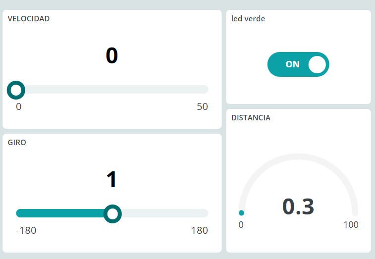
Resultado
GPIO del ESP32
Mapa de los pines en el Arduino Nano ESP32
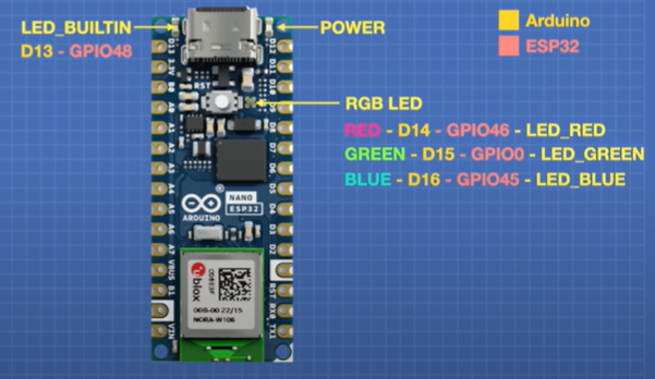
Extraído de Youtube Exploring the Arduino Nano ESP32
Como podemos observar, nuestro objetivo pues es el GPIO0
¿Dónde está físicamente los GPIO ?
Pues como podemos ver en este esquema el GPIO0 está en el pin BOOT1

Fuente CC-BY-SA https://docs.arduino.cc/tutorials/alvik/user-manual/
-
SI USAMOS MICROPYTHON TENEMOS QUE USAR LAS VERDES
-
SI USAMOS CÓDIGO ARDUINO IDE TENEMOS QUE USAR LAS ROJAS
Como puedes observar, si cortocircuitas B1 = GPI0 = D15 con GND enciende el led RGB en color verdel esto pasa si Pones la placa en modo Bootloader.
Arduino IDE con IoT: ESP32 + Sensores externos + IoT
OBJETIVO
Ahora vamos a utilizar el ESP32 SIN EL ARDUINO ALVIK podemos sacar la placa microcontroladora y ponerlo en una placa protoboard y experimentar con sensores y actuadores estándares en el mercado :
 +
+ 
Para ver varias posibilidades, vamos a ver estos sensores y actuadores (recomendamos ver estas páginas actuadores y sensores)
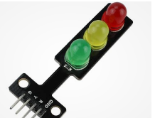
- Un led de salida simple, para practicar salida digital en mi caso voy a elegir este gracioso semáforo
- Un sensor LDR pero para practicar los dos tipos de señal,
- con salida analógica
- con salida digital.
- Un sensor CO2 CCS811 con protocolo I2C
+ +
+ +
+
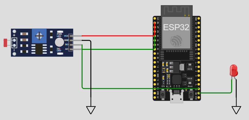
ESQUEMA DE CONEXIONES
- SEMAFORO
- LED ROJO al D1 del ESP32
- GND a GND
- MODULO SENSOR LDR
- SEÑAL DIGITAL al D0 del ESP32
- SEÑAL ANALÓGICA al A0 del ESP32
- VCC a 3V3
- GND A GND
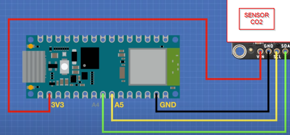
- MODULO SENSOR CO2
- SCL al pin A5 del ESP32
- SDA al pin A4 del ESP32
- PIN WAKE a GND
- VCC a 3V3
- GND A GND
DEVICES
Nos vamos a Arduino Cloud, y en DEVICES añadimos el ESP32 y obtenemos el TOKEN o palabra secreta (si has hecho la práctica anterior, no es necesario pues ya tenemos el TOKEN o palabra secreta) como es similar al caso anterior, no lo desarrollamos. (Nos pedirá también el SSID y la contraseña de la red wifi)
VARIABLES
Añadimos las siguientes variables :
- CO2 tipo int y Read
- luz tipo int y Read
- luzdigital tipo bool y Read
- rojo tipo bool y Read&Write
EL SCKETCH -LIBRERIA CCS811
Primero añadiríamos la librería de keystudio https://fs.keyestudio.com/KS0457 pero no lo permite Arduino Cloud, viendo las instrucciones, vemos que son las mismas que en los ejemplos de esta librería la de DF que es la que instalamos :
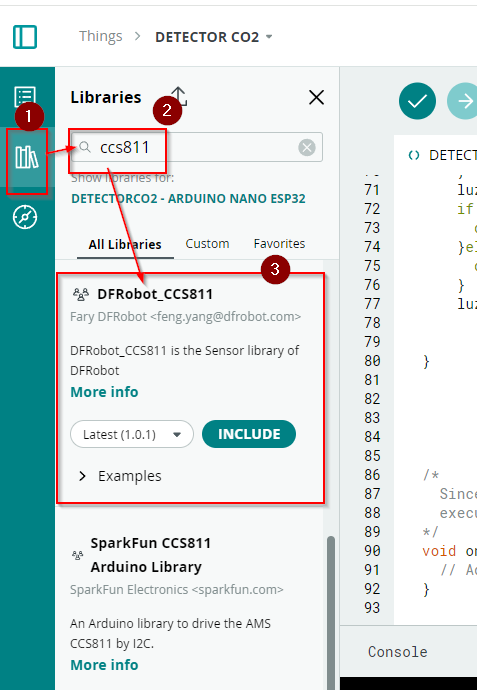
esto provoca la incorporación de la línea 1 #include <DFRobot_CCS811.h>
EL SCKETCH -EL CÓDIGO
- Tenemos las variables definidas en las líneas 10-13 :
- int cO2;
- int luz;
- bool luzdigital;
- bool rojo;
- Definimos una variable de tipo el sensor CCS811 en la línea 23 DFRobot_CCS811 CCS811;
- En Setup en las líneas 48-21 arrancamos ese sensor:
- while(CCS811.begin() != 0){
Serial.println("failed to init chip, please check if the chip connection is fine");
delay(1000);
}
- while(CCS811.begin() != 0){
- Definimos los pines digitales 0 y 1 como entrada y salida respectivamente:
- pinMode(1,OUTPUT);
pinMode(0,INPUT);
- pinMode(1,OUTPUT);
- En las líneas 60-70 que lea el CCS811 y la parte de CO2 que lo meta en la variable CO2 (línea 63)
- if(CCS811.checkDataReady() == true){
Serial.print("CO2: ");
Serial.print(CCS811.getCO2PPM());
cO2=CCS811.getCO2PPM();
Serial.print("ppm, TVOC: ");
Serial.print(CCS811.getTVOCPPB());
Serial.println("ppb");
} else {
Serial.println("Data is not ready!");
}
- if(CCS811.checkDataReady() == true){
- En las línea 71 que luz sea la lectura del pin A0 luz = analogRead(A0);
- En las líneas 72-76 que según rojo se encienda o no el led
- if (rojo){
digitalWrite(1,HIGH);
}else{
digitalWrite(1,LOW);
}
- if (rojo){
- En la línea 77 que luzdigital sea la lectura de la salida digital del sensor LDR
- luzdigital=digitalRead(0);
#include <DFRobot_CCS811.h>
/*
Sketch generated by the Arduino IoT Cloud Thing "Untitled"
https://create.arduino.cc/cloud/things/17c10209-3874-430a-877c-c082ff7dd38d
Arduino IoT Cloud Variables description
The following variables are automatically generated and updated when changes are made to the Thing
int cO2;
int luz;
bool luzdigital;
bool rojo;
Variables which are marked as READ/WRITE in the Cloud Thing will also have functions
which are called when their values are changed from the Dashboard.
These functions are generated with the Thing and added at the end of this sketch.
*/
#include "thingProperties.h"
//DFRobot_CCS811 CCS811(&Wire, /*IIC_ADDRESS=*/0x5A);
DFRobot_CCS811 CCS811;
void setup() {
// Initialize serial and wait for port to open:
Serial.begin(9600);
// This delay gives the chance to wait for a Serial Monitor without blocking if none is found
delay(1500);
// Defined in thingProperties.h
initProperties();
// Connect to Arduino IoT Cloud
ArduinoCloud.begin(ArduinoIoTPreferredConnection);
/*
The following function allows you to obtain more information
related to the state of network and IoT Cloud connection and errors
the higher number the more granular information you’ll get.
The default is 0 (only errors).
Maximum is 4
*/
setDebugMessageLevel(2);
ArduinoCloud.printDebugInfo();
while(CCS811.begin() != 0){
Serial.println("failed to init chip, please check if the chip connection is fine");
delay(1000);
}
pinMode(1,OUTPUT);
pinMode(0,INPUT);
}
void loop() {
ArduinoCloud.update();
// Your code here
if(CCS811.checkDataReady() == true){
Serial.print("CO2: ");
Serial.print(CCS811.getCO2PPM());
cO2=CCS811.getCO2PPM();
Serial.print("ppm, TVOC: ");
Serial.print(CCS811.getTVOCPPB());
Serial.println("ppb");
} else {
Serial.println("Data is not ready!");
}
luz = analogRead(A0);
if (rojo){
digitalWrite(1,HIGH);
}else{
digitalWrite(1,LOW);
}
luzdigital=digitalRead(0);
}
/*
Since Rojo is READ_WRITE variable, onRojoChange() is
executed every time a new value is received from IoT Cloud.
*/
void onRojoChange() {
// Add your code here to act upon Rojo change
}DASHBOARD
- Un gauge ligado a CO2 desde 0 a 2000
- Un gauge ligado a Luz de 0 a 2.200
- Un Switch ligado a rojo
- Un led de oscuridad ligado a luzdigital
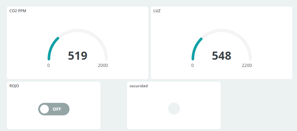
Alternativa : en vez de luz tendría que llamarse "oscuridad" que sea luz pero que vaya al revés
RESULTADO
ALTERNATIVA: Que el semáforo visualice los niveles peligrosos de CO2, por ejemplo el umbral del amarillo 600-1.000
¿Te atreves a poner un servomotor?
Predictor meteorológico
Predictor meteorológico
Autor Mario Monteagudo Asesor digital Centro de Profesorado de Ejea de los Caballeros
Usando IDE Arduino y el sensor Bosch BME280 se puede medir la presión atmosférica, temperatura y humedad y usando un código predictivo Algoritmo de Zambretti que usa las diferencias de presiones cada 3 horas, puede hacer pronóscticos. Para ello mide la presión cada 5 minutos y tienen en cuenta la altitud del lugar y la temperatura.
El ESP32 tendría que estar en el exterior y como hemos explicado, necesita 3 horas para hacer su primera predicción.
Este es el resultado
Y este es el código
#include "arduino_secrets.h"
//Predictor del tiempo mediante el algoritmo de Zambretti************************
//2024*Mario Monteagudo Alda*****mario.monteagudo@cpejea.es**********************
#include "arduino_secrets.h"
#include <SimpleBME280.h> //Biblioteca usada para el sensor
const float ALTURA = 497.0; //Altitud del lugar
SimpleBME280 bme280; //Declaración de la instancia del sensor
float presiones[37]; //Presiones corregidas cincominutales de las 3 últimas horas
int zambretti; //Número de Zambretti
float temperatura; //ºC
float humedad; //Humedad relativa en %
float presion; //Presión atmosférica en mbar
int contador = 0; //Contador de número de medidas de presión cincominutales tomadas
bool encendido = false; //Bandera para intermitencia del LED
/*
Arduino IoT Cloud Variables description
The following variables are automatically generated and updated when changes are made to the Thing
String boletin;
float fiabilidad;
float tendencia;
Variables which are marked as READ/WRITE in the Cloud Thing will also have functions
which are called when their values are changed from the Dashboard.
These functions are generated with the Thing and added at the end of this sketch.
*/
#include "thingProperties.h"
void setup() {
pinMode(LED_BUILTIN,OUTPUT);
digitalWrite(LED_BUILTIN,HIGH);
// Inicialización de la comunicación serie y espera
Serial.begin(19200);
delay(2000);
// Defined in thingProperties.h
initProperties();
// Connect to Arduino IoT Cloud and wait
ArduinoCloud.begin(ArduinoIoTPreferredConnection, false);
delay(2000);
/*
The following function allows you to obtain more information
related to the state of network and IoT Cloud connection and errors
the higher number the more granular information you’ll get.
The default is 0 (only errors).
Maximum is 4
*/
setDebugMessageLevel(2);
ArduinoCloud.printDebugInfo();
bme280.begin(); //Inicialización del sensor y espera
delay(2000);
//Primera lectura del sensor
bme280.update();
presion = bme280.getP();
temperatura = bme280.getT();
//Corrección de la presión según la altitud y temperatura y paso de Pa a mbar
presion = (presion * pow(1 - (0.0065 * ALTURA) / (temperatura + (0.0065 * ALTURA) + 273.15),-5.257 ))/100.0;
for (int i=0; i<=36; i++) { presiones[i]=presion;}
fiabilidad = 0;
}
void loop() {
bme280.update();
presion = bme280.getP();
temperatura = bme280.getT();
humedad = bme280.getH();
presion = (presion * pow(1 - (0.0065 * ALTURA) / (temperatura + (0.0065 * ALTURA) + 273.15),-5.257 ))/100.0;
tendencia=presion-presiones[0];
for (int i=0; i<36; i++) { presiones[i]=presiones[i+1];}
presiones[36] = presion;
//Cálculo del número de Zambretti
if ((tendencia <= -1.6) & (presion > 985.0) & (presion < 1050.0)) {zambretti = round(127-0.12*presion);}
else if ((tendencia >= 1.6) & (presion > 947.0) & (presion < 1030.0)) {zambretti = round(185-0.16*presion);}
else if ((abs(tendencia) < 1.6) & (presion > 960.0) & (presion < 1033.0)) {zambretti = round(144-0.13*presion);}
else {zambretti = 0;}
//Boletín con el pronóstico
boletin = "Temperatura: " + String(temperatura,1) + " ºC" + "\n" +
"Humedad relativa: " + String(humedad,1) + " %" + "\n" +
"Presión: " + String(presion,0) + " mbar" + "\n" +
"Tendencia: " + String(tendencia,2) + " mbar" + "\n" +
pronostico(zambretti);
Serial.println(boletin + "\n");
//Espera de cinco minutos para la actualización
unsigned long tiempo = millis();
while ((millis()-tiempo) < 5*60*1000 )
{
ArduinoCloud.update();
delay(1000);
encendido = !encendido;
digitalWrite(LED_BUILTIN,encendido);
}
contador = min(36, contador + 1);
//Después de tres horas de medidas, la fiabilidad es del 100%
fiabilidad = map(contador, 0, 36, 0, 100);
}
//Cadena de texto con el pronóstico meteorológico***********************
String pronostico(int z)
{
switch (z)
{
case 1:
return "Tiempo estable"; break;
case 2:
return "Buen tiempo"; break;
case 3:
return "Buen tiempo con ligera inestabilidad"; break;
case 4:
return "Buen tiempo evolucionando a chubascos"; break;
case 5:
return "Chubascos evolucionando a tiempo inestable"; break;
case 6:
return "Inestable evolucionando a lluvioso"; break;
case 7:
return "Intervalos de lluvia con empeoramiento"; break;
case 8:
return "Intervalos de lluvia evolucionando a gran inestabilidad"; break;
case 9:
return "Muy inestable con lluvia"; break;
case 10 :
return "Tiempo estable"; break;
case 11:
return "Buen tiempo"; break;
case 12:
return "Buen tiempo con posibles chubascos"; break;
case 13:
return "Buen tiempo con probables chubascos"; break;
case 14:
return "Chubascos con intervalos despejados"; break;
case 15:
return "Variable con algo de lluvia"; break;
case 16:
return "Inestable con intervalos de lluvia"; break;
case 17:
return "Lluvia a intervalos frecuentes"; break;
case 18:
return "Muy inestable con lluvia"; break;
case 19:
return "Tormentoso con lluvia abundante"; break;
case 20 :
return "Tiempo estable"; break;
case 21:
return "Buen tiempo"; break;
case 22:
return "Evolucionando a buen tiempo"; break;
case 23:
return "Buen tiempo evolucionando a mejor"; break;
case 24:
return "Buen tiempo con posibles chubascos a primeras horas"; break;
case 25:
return "Chubascos a primeras horas evolucionando a mejor"; break;
case 26:
return "Variable evolucionando a mejor"; break;
case 27:
return "Inestable a primeras horas evolucionando a estable"; break;
case 28:
return "Inestable con probable mejoría"; break;
case 29:
return "Inestable con breves intervalos de buen tiempo"; break;
case 30:
return "Muy inestable con intervalos de buen tiempo"; break;
case 31:
return "Tormentoso con probable mejoría"; break;
case 32:
return "Tormentoso con mucha lluvia"; break;
default:
return "Tiempo indeterminado";
}
}