# Arduino IDE

# Conexión con Arduino IDE

El software Arduino IDE lo puedes descargar en [https://www.arduino.cc/](https://www.arduino.cc/)

[![2024-12-27 08_48_07-Software _ Arduino.png](https://libros.catedu.es/uploads/images/gallery/2024-12/scaled-1680-/2024-12-27-08-48-07-software-arduino.png)](https://libros.catedu.es/uploads/images/gallery/2024-12/2024-12-27-08-48-07-software-arduino.png)

Una vez instalado vamos a ver cómo podemos programar con el software de Arduino nuestro Picobriks

<p class="callout warning">No sigas las instrucciones de Project Book aquí [https://picobricks.com/pages/projectbook](https://picobricks.com/pages/projectbook) **NO funcionan**.   
Las siguientes instrucciones **sí que funcionan** y son de  ***[Bricogeek](https://lab.bricogeek.com/tutorial/como-programar-raspberry-pi-pico-con-arduino/configurar-ide-de-arduino-para-raspberry-pi-pico)** Licencia CC-BY  
 (hay muchas páginas con las mismas instrucciones pon en un buscador raspberry pico arduino ide )*</p>

Nos vamos a **Archivo-Preferencias** y le decimos que ponga el siguiente directorio para las librerías :

[![2024-12-27 23_43_03-Editing Page Conexión con Arduino IDE _ Librería CATEDU.png](https://libros.catedu.es/uploads/images/gallery/2024-12/scaled-1680-/2024-12-27-23-43-03-editing-page-conexion-con-arduino-ide-libreria-catedu.png)](https://libros.catedu.es/uploads/images/gallery/2024-12/2024-12-27-23-43-03-editing-page-conexion-con-arduino-ide-libreria-catedu.png)
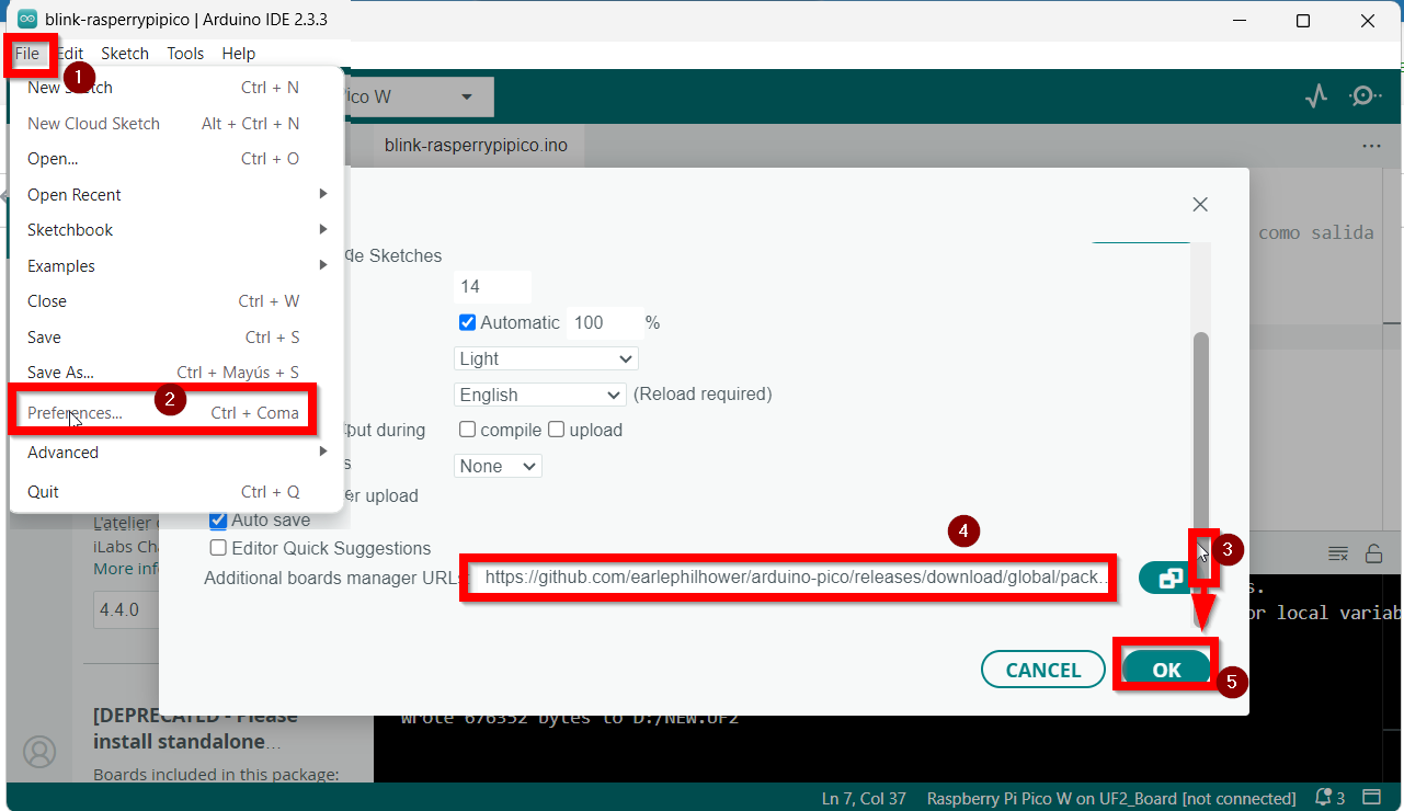
Esta es la URL que pegar para que cargue placas que no vienen por defecto :

```c
https://github.com/earlephilhower/arduino-pico/releases/download/global/package_rp2040_index.json
```

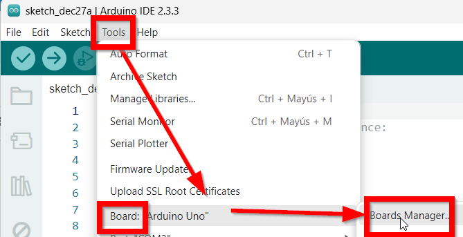
Una vez puesto nos vamos a **Boards manager**..

[![2024-12-27 08_50_07-sketch_dec27a _ Arduino IDE 2.3.3.png](https://libros.catedu.es/uploads/images/gallery/2024-12/scaled-1680-/2024-12-27-08-50-07-sketch-dec27a-arduino-ide-2-3-3.png)](https://libros.catedu.es/uploads/images/gallery/2024-12/2024-12-27-08-50-07-sketch-dec27a-arduino-ide-2-3-3.png)
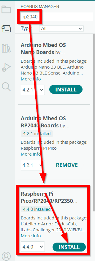
Y ponemos **RP2040** en el buscador, aparecerá este software, **Raspberry Pi Pico/RP2040** Lo instalamos

[![2024-12-27 23_54_30-blink-rasperrypipico _ Arduino IDE 2.3.3.png](https://libros.catedu.es/uploads/images/gallery/2024-12/scaled-1680-/2024-12-27-23-54-30-blink-rasperrypipico-arduino-ide-2-3-3.png)](https://libros.catedu.es/uploads/images/gallery/2024-12/2024-12-27-23-54-30-blink-rasperrypipico-arduino-ide-2-3-3.png)
<p class="callout warning"><span style="color: rgb(0, 0, 0);">{{@12670#bkmrk-atenci%C3%93n-desconectam}}</span></p>

Una vez puesto en modo Booloader seleccionamos la placa **Raspberry Pi Pico W** (4) y también seleccionamos el puerto (5) **UF2\_Board**

[![2024-12-27 23_57_06-.png](https://libros.catedu.es/uploads/images/gallery/2024-12/scaled-1680-/2024-12-27-23-57-06.png)](https://libros.catedu.es/uploads/images/gallery/2024-12/2024-12-27-23-57-06.png)
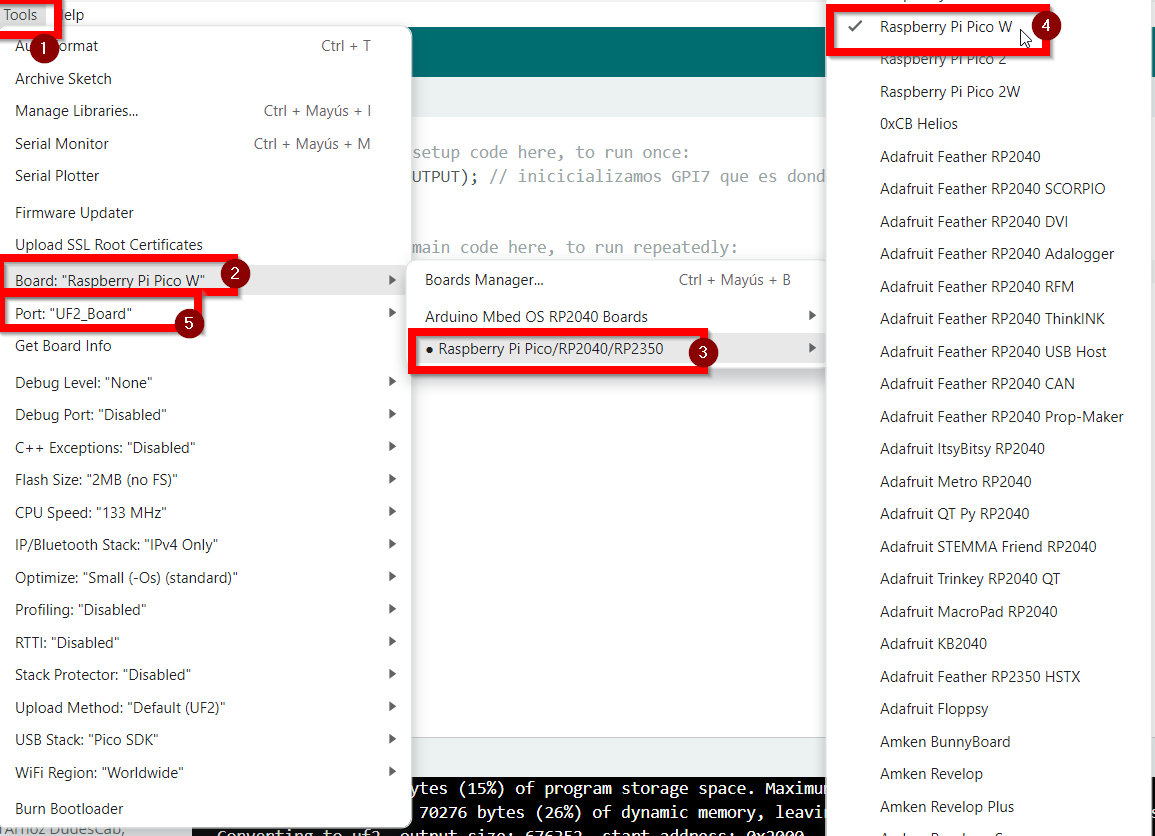
También puede salir otro tipo de puerto como este que dice que es el RP2040 Rasbberry Pi Pico W

[![2024-12-28 00_00_32-.png](https://libros.catedu.es/uploads/images/gallery/2024-12/scaled-1680-/2024-12-28-00-00-32.png)](https://libros.catedu.es/uploads/images/gallery/2024-12/2024-12-28-00-00-32.png).

En resumen tiene que salir abajo a la derecha que esta conectado

[![2024-12-27 08_59_03-sketch_dec27a _ Arduino IDE 2.3.3.png](https://libros.catedu.es/uploads/images/gallery/2024-12/scaled-1680-/2024-12-27-08-59-03-sketch-dec27a-arduino-ide-2-3-3.png)](https://libros.catedu.es/uploads/images/gallery/2024-12/2024-12-27-08-59-03-sketch-dec27a-arduino-ide-2-3-3.png)

# El primer programa con Arduino IDE: Blink

Entramos en Arduino IDE configurado según la página anterior (Board: Raspberry Pi y el puerto COM que corresonda) y pegamos el siguiente código:

```c
void setup() {
  // put your setup code here, to run once:
  pinMode(7, OUTPUT); // inicicializamos GPI7 que es donde esta el ledrojo como salida
}
void loop() {
  // put your main code here, to run repeatedly:
  digitalWrite(7, HIGH); //encendemos led rojo 
  delay(1000); //espera 1 segundo         
  digitalWrite(7, LOW); //apagamos led rojo
  delay(1000); //espera 1 segundo                  
}
```

Ponemos el código en el área **1,** pulsamos **2** para compilar, y finalmente **3** para que lo suba a PicoBricks, cuando aparezca el mensaje **wrote...** en 4 ya podemos ver que el led rojo empieza a parpadear

[![2024-12-28 08_38_02-blink-rasperrypipico _ Arduino IDE 2.3.3.png](https://libros.catedu.es/uploads/images/gallery/2024-12/scaled-1680-/2024-12-28-08-38-02-blink-rasperrypipico-arduino-ide-2-3-3.png)](https://libros.catedu.es/uploads/images/gallery/2024-12/2024-12-28-08-38-02-blink-rasperrypipico-arduino-ide-2-3-3.png)
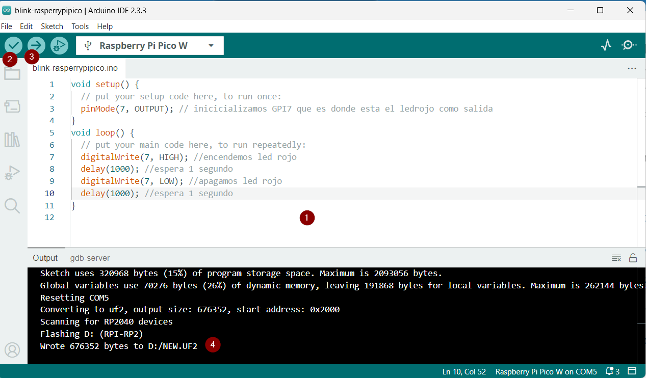
<p class="callout success">Por cierto, el programa **se queda cargado** pruébalo! desenchúfalo del ordenador, alimenta PicoBricks con un PowerBank o un cargador de móvil con el cabla USB y ¡¡ **sigue funcionando !!!**</p>

# Proyectos

{{@12689}}

# Proyectos con Wifi

##### <span style="color: rgb(22, 145, 121);">**<span class="wp-dark-mode-bg-image"><span class="wp-dark-mode-bg-image">ScanNetworks</span></span><span class="wp-dark-mode-bg-image"> </span>**</span>

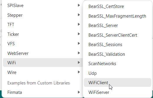
Podemos ir a Ejemplos y vamos a ejecutar el **ScanNetworks** que no requiere contraseñas de wifi

[![2025-01-04 20_11_51-.png](https://libros.catedu.es/uploads/images/gallery/2025-01/scaled-1680-/2025-01-04-20-11-51.png)](https://libros.catedu.es/uploads/images/gallery/2025-01/2025-01-04-20-11-51.png)
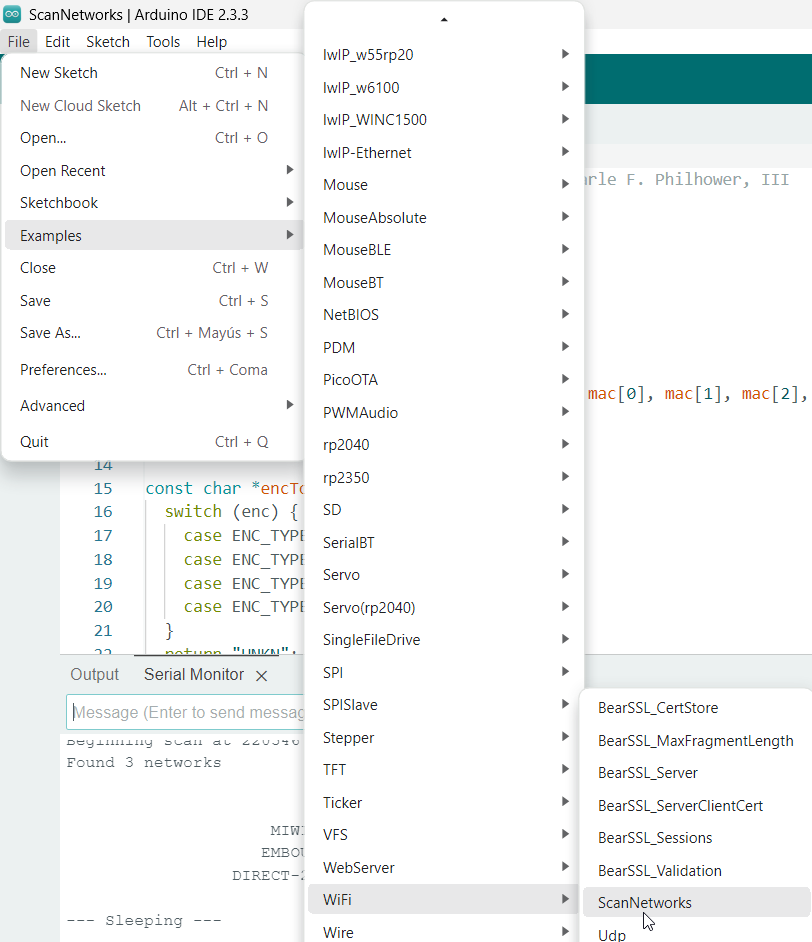
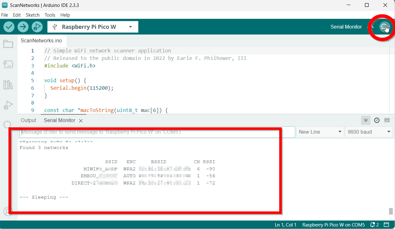
Al ejecutarlo nos sale en la ventana de monitor serie las wifis que encuentra

[![2025-01-04 20_13_59-ScanNetworks _ Arduino IDE 2.3.3.png](https://libros.catedu.es/uploads/images/gallery/2025-01/scaled-1680-/2025-01-04-20-13-59-scannetworks-arduino-ide-2-3-3.png)](https://libros.catedu.es/uploads/images/gallery/2025-01/2025-01-04-20-13-59-scannetworks-arduino-ide-2-3-3.png)
##### <span style="color: rgb(22, 145, 121);">**WifiClient**</span>

Si nos vamos a este ejemplo:

[![2025-01-04 20_31_01-.png](https://libros.catedu.es/uploads/images/gallery/2025-01/scaled-1680-/2025-01-04-20-31-01.png)](https://libros.catedu.es/uploads/images/gallery/2025-01/2025-01-04-20-31-01.png)

Tenemos que ir a las líneas 9 y 10 para poner nuestra wifi y contraseña:

```c
#define STASSID "aquituwifi"
#define STAPSK "aqui tu contraseña"
```

Al ejecutarlo llama a esta dirección definida en las líneas 16 y 17

```
const char* host = "djxmmx.net";
const uint16_t port = 17;
```

Y sale **la cita del día** cada 5 minutos en el puerto serie

```

WiFi connected
IP address: 
192.168.1.48
connecting to djxmmx.net:17
sending data to server
receiving from remote server
"Thomas wants to get it in quickly, and...Now there's a steal by Bird!
 Underneath to DJ, lays it in!
 1 second left, what a play by Bird!"
	 - 1987 NBA Eastern Conference Finals

closing connection
connecting to djxmmx.net:17
sending data to server
receiving from remote server
"Oh oh oh oh oh ooh, why'd you have to go oh, away from all, me love, why you leave me, w-why you leave me?..."
	 - Sean Kingston (Me Love)

closing connection
connecting to djxmmx.net:17
sending data to server
receiving from remote server
"I wanna run away, with you, cuz baby you're my everything..."
	 - Frankie J. (Run Away)

closing connection
```

##### <span style="color: rgb(22, 145, 121);">**Encender y apagar un led**</span>

De [https://dronebotworkshop.com/picow-arduino/](https://dronebotworkshop.com/picow-arduino/) hemos conseguido este código, donde Raspberry actúa como cliente, pero esta pensado para encender y apagar el led integrado en la Rasberry Pi Pico W, así que le hemos añadido el Led rojo de PicoBrick que esta en GPI7

- En la línea 43 el pin 7 como salida **pinMode(7,OUTPUT);**
- En la línea 97 que encienda el pin 7 también **digitalWrite(7, HIGH);**
- En la línea 102 que apague el pin 7 también **digitalWrite(7, LOW);**
- Acuérdate de poner en las líneas 17 y 18 tu wifi

```c
/*
  Pico W Web Interface Demo
  picow-web-control-demo.ino
  Web Interface & WiFi Connection
  Control the onboard LED with Pico W

  Adapted from ESP32 example by Rui Santos - https://randomnerdtutorials.com

  DroneBot Workshop 2022
  https://dronebotworkshop.com
*/

// Load Wi-Fi library
#include <WiFi.h>

// Replace with your network credentials
const char* ssid = "pontuwifi";
const char* password = "pontucontraseña";

// Set web server port number to 80
WiFiServer server(80);

// Variable to store the HTTP request
String header;

// Variable to store onboard LED state
String picoLEDState = "off";

// Current time
unsigned long currentTime = millis();
// Previous time
unsigned long previousTime = 0;
// Define timeout time in milliseconds (example: 2000ms = 2s)
const long timeoutTime = 2000;

void setup() {

  // Start Serial Monitor
  Serial.begin(115200);

  // Initialize the LED as an output
  pinMode(LED_BUILTIN, OUTPUT);
  pinMode(7,OUTPUT);//initialize digital pin 7 as an output

  // Set LED off
  digitalWrite(LED_BUILTIN, LOW);

  // Connect to Wi-Fi network with SSID and password
  WiFi.begin(ssid, password);

  // Display progress on Serial monitor
  while (WiFi.status() != WL_CONNECTED) {
    delay(500);
    Serial.print(".");
  }

  // Print local IP address and start web server
  Serial.println("");
  Serial.print("WiFi connected at IP Address ");
  Serial.println(WiFi.localIP());

  // Start Server
  server.begin();
}

void loop() {

  WiFiClient client = server.available();   // Listen for incoming clients

  if (client) {                             // If a new client connects,
    currentTime = millis();
    previousTime = currentTime;
    Serial.println("New Client.");          // print a message out in the serial port
    String currentLine = "";                // make a String to hold incoming data from the client
    while (client.connected() && currentTime - previousTime <= timeoutTime) {  // loop while the client's connected
      currentTime = millis();
      if (client.available()) {             // if there's bytes to read from the client,
        char c = client.read();             // read a byte, then
        Serial.write(c);                    // print it out the serial monitor
        header += c;
        if (c == '\n') {                    // if the byte is a newline character
          // if the current line is blank, you got two newline characters in a row.
          // that's the end of the client HTTP request, so send a response:
          if (currentLine.length() == 0) {
            // HTTP headers always start with a response code (e.g. HTTP/1.1 200 OK)
            // and a content-type so the client knows what's coming, then a blank line:
            client.println("HTTP/1.1 200 OK");
            client.println("Content-type:text/html");
            client.println("Connection: close");
            client.println();

            // Switch the LED on and off
            if (header.indexOf("GET /led/on") >= 0) {
              Serial.println("LED on");
              picoLEDState = "on";
              digitalWrite(LED_BUILTIN, HIGH);
              digitalWrite(7, HIGH);
            } else if (header.indexOf("GET /led/off") >= 0) {
              Serial.println("LED off");
              picoLEDState = "off";
              digitalWrite(LED_BUILTIN, LOW);
              digitalWrite(7, LOW);
            }

            // Display the HTML web page
            client.println("<html>");
            client.println("<head><meta name=\"viewport\" content=\"width=device-width, initial-scale=1\">");
            client.println("<link rel=\"icon\" href=\"data:,\">");

            // CSS to style the on/off buttons
            client.println("<style>html { font-family: Helvetica; display: inline-block; margin: 0px auto; text-align: center;}");
            client.println(".button { background-color: #4CAF50; border: none; color: white; padding: 16px 40px;");
            client.println("text-decoration: none; font-size: 30px; margin: 2px; cursor: pointer;}");
            client.println(".button2 {background-color: #F23A3A;}</style></head>");

            // Web Page Heading
            client.println("<body><h1>Pico W LED Control</h1>");

            // Display current state, and ON/OFF buttons for Onboard LED
            client.println("<p>Onboard LED is " + picoLEDState + "</p>");
            
            // Set buttons
            if (picoLEDState == "off") {
              
              //picoLEDState is off, display the ON button
              client.println("<p><a href=\"/led/on\"><button class=\"button\">ON</button></a></p>");
            } else {

              //picoLEDState is on, display the OFF button
              client.println("<p><a href=\"/led/off\"><button class=\"button button2\">OFF</button></a></p>");
            }

            client.println("</body></html>");

            // The HTTP response ends with another blank line
            client.println();
            // Break out of the while loop
            break;
          } else { // if you got a newline, then clear currentLine
            currentLine = "";
          }
        } else if (c != '\r') {  // if you got anything else but a carriage return character,
          currentLine += c;      // add it to the end of the currentLine
        }
      }
    }
    // Clear the header variable
    header = "";
    // Close the connection
    client.stop();
    Serial.println("Client disconnected.");
    Serial.println("");
  }
}

```

Al ejecutarlo, nos aparece por el puerto serie la IP que se ha conectado:

[![2025-01-04 21_41_16-encender-apagar-led-picobricks-wifi _ Arduino IDE 2.3.3.png](https://libros.catedu.es/uploads/images/gallery/2025-01/scaled-1680-/2025-01-04-21-41-16-encender-apagar-led-picobricks-wifi-arduino-ide-2-3-3.png)](https://libros.catedu.es/uploads/images/gallery/2025-01/2025-01-04-21-41-16-encender-apagar-led-picobricks-wifi-arduino-ide-2-3-3.png)
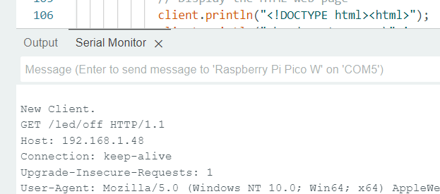
Entramos en un navegador en un ordenador conectado a la misma wifi en la dirección 192.168.1.48 y este es el resultado:

<iframe allow="accelerometer; autoplay; clipboard-write; encrypted-media; gyroscope; picture-in-picture; web-share" allowfullscreen="allowfullscreen" frameborder="0" height="634" src="https://www.youtube.com/embed/haE4GdOd4zo" title="encendido apagado led con Raspberry Pi Pico W y Arduino IDE de Picobricks" width="356"></iframe>

##### <span style="color: rgb(22, 145, 121);">**¿Y con un servo?**</span>

Si tienes un servo puedes conectarlo y también puedes utilizar el código que aparece en De [https://dronebotworkshop.com/picow-arduino/](https://dronebotworkshop.com/picow-arduino/) con las conexiones que indican

</body></html>